How to Make a Custom Door or Window Symbol in Vectorworks
Use the parametric Door and Window tools in early design phases for planning the general size and placement of units.
When you eventually need geometry that’s more specific than the parametric tools allow, you can replace these with custom symbols.
Follow the 8 steps below to create custom 2D/3D symbols in Vectorworks that automatically insert into Walls.

STEP 1
CREATE 3D MODEL OF DOOR OR WINDOW
Use 3D tools such as Extrude and Extrude Along Path to model the unit. This tutorial uses a door as an example, though this process also works with windows, fireplaces, and any symbols that would insert into walls.
If you’d like to download a file with a 3D model to use for this tutorial, click below.

STEP 2
SAVE THE DOOR ASSEMBLY AS A SYMBOL
Set your view to Top/Plan. Select all the 3D objects comprising the door unit and go to Modify > Create Symbol.
Give it a name, then match the settings seen in the screenshot (except for “Assign to Class“ which is up to you… default is <Active Class>).
Make sure “Next Mouse Click” is set to “Insertion Point.”

STEP 3
CHOOSE INSERTION POINT
After clicking OK in the dialogue box, you still need to choose an insertion point. It is imperative to do this accurately. On the X axis this should be placed in the center of the doorway, and the Y axis should be where the plane of the wall surface would be (i.e. on one side of the jamb, typically).
Because you’re in Top/Plan, the Z of the insertion point is automatically at the ground plane (+0”).

STEP 4
CREATE THE 2D COMPONENT OF THE SYMBOL
The 2D Component (“Top”) displays when in Top/Plan view and can contain any 2D objects as needed (lines, rectangles, arcs, other 2D symbols, etc.). To see the existing 3D geometry for snapping reference, use the floating “Component Edit” toolbar to set “Show Other” to “3D.”
The plan representation is often simplified compared to the 3D model, and they don’t have to match entirely. For example, the 2D Component typically shows the door open with an arc for the door swing, while the 3D Component keeps the door shut so it’s visible in elevations taken from the 3D model. Your drafting conventions may differ.
If you’re familiar with using Auto Hybrid objects, some elements of the 2D Component could be auto-generated from the existing 3D objects. For example, you could go into the 3D Component, select the jamb, choose the Auto Hybrid command, then set up the parameters to show the sides of the jamb as hatched and the overhead jamb as dashed (see VW Help for more info on Auto Hybrids if needed). The alternative to this is manually drawing two hatched rectangles and two dashed lines directly in the 2D Component. Either way works.
Click the button below if you’d like to download an in-progress 2D/3D symbol that’s ready for the next step.

STEP 5
INSERT SYMBOL INTO WALL
Inserting the symbol into a wall will help visualize the next two steps. To do so, draw a wall using the Wall tool, then drag your symbol onto the wall, or insert a new instance via the Resource Manager.
When inserting a symbol into a wall, the wall will highlight in red. If this is not happening, make sure “Wall Insertion Mode” is turned on in the mode bar.
Note in the Object Info Palette that you can align the inserted symbol with the Left or Right side of the wall. This is in reference to the insertion point defined in the previous step. You can also use the flip button if needed.
STEP 6
DEFINE HOW THE SYMBOL BREAKS THE WALL IN 2D
Go into the 2D Component and add two locus points (shortcut: zero) to define where the symbol breaks a wall when inserted. These are typically placed on the outer sides of the jamb (placement on X axis is all that matters).
Although loci never print, it’s recommended to place these on the NonPlot class, allowing you to hide their display.

STEP 7
DEFINE HOW THE SYMBOL CUTS INTO 3D WALLS
By default, a symbol inserted into a wall will use an automatically-created “wall hole” (i.e. the volume subtracted from the 3D wall), though if your symbol includes things that extend beyond the wall opening, such as casing/trim, then you need to manually define the wall hole.
Right click the symbol and choose “Edit 3D Wall Hole Component.” This Component is currently empty, and the goal is to add a 3D object that will act like a “Subtract Solid” from any walls the symbol is inserted into.
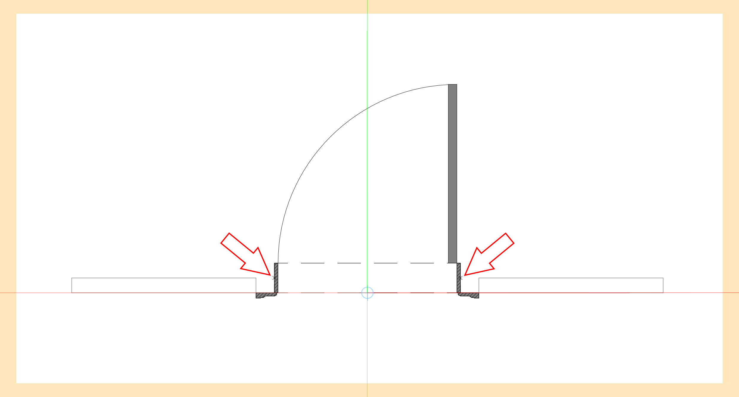
You should be able to see the 3D Component of your symbol in grey which you can use as a guide (if not turn on “Show Other Objects While in Edit Modes”). In top view, draw a rectangle that snaps to the outer corners of the jamb, then extrude it upwards to match the opening (in this case 7’-1½”). Check in 3D that this object matches the intended opening.
Sometimes it can be easier to simply copy the 3D jamb from your symbol’s 3D Component, then go into 3D Wall Hole Component and Edit > Paste In Place. This can then be used as reference for creating the wall hole object, or can be used directly by modifying the extrude as needed.
Any 3D shape placed in the 3D Wall Hole Component will be subtracted from the wall, so the specifics will always depend on the design of the unit and may be more complex.

STEP 8
CONFIRM THAT EVERYTHING WORKS
Insert your door into a few different types of walls and make sure it works as expected, both in 2D and 3D. Make modifications to the symbol definition as necessary.
Click the button below if you’d like to download the finished 2D/3D custom door to compare with yours.
STEP 9 (Optional)
INSERT AS PART OF DOOR TOOL
If you want your custom door to be a “Door” object for data reporting purposes (i.e. worksheets), or if you need to utilize the “Offset in Wall” parameter (which would give you additional control when inserting into walls of different thicknesses, for example), then delete any instances of your symbol and place a regular door into the wall using the Door tool.
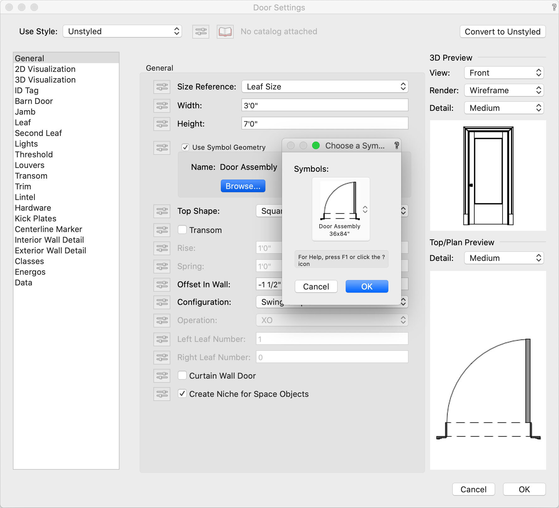
Then in the Door’s Object Info Palette, click the “Settings” button, and in the General category check “Use Symbol Geometry.” Click the Browse button to choose the symbol you made. Click OK. Adjust the “Offset in Wall” parameter as needed. Note that although it’s a Door object, your symbol is replacing all of the parametric settings, so fields like Width and Height won’t affect your custom door.
I personally leave my custom Doors and Windows as regular 2D/3D Symbols inserted into Walls.
I’d love to hear from you if you have questions or feedback! Click the button below to email me.
If you found this tutorial helpful and would like to help keep me caffeinated for making more, I’m on Venmo @AndyBroomell
